
Optimizing CNC Performance with Touch Probe Calibration
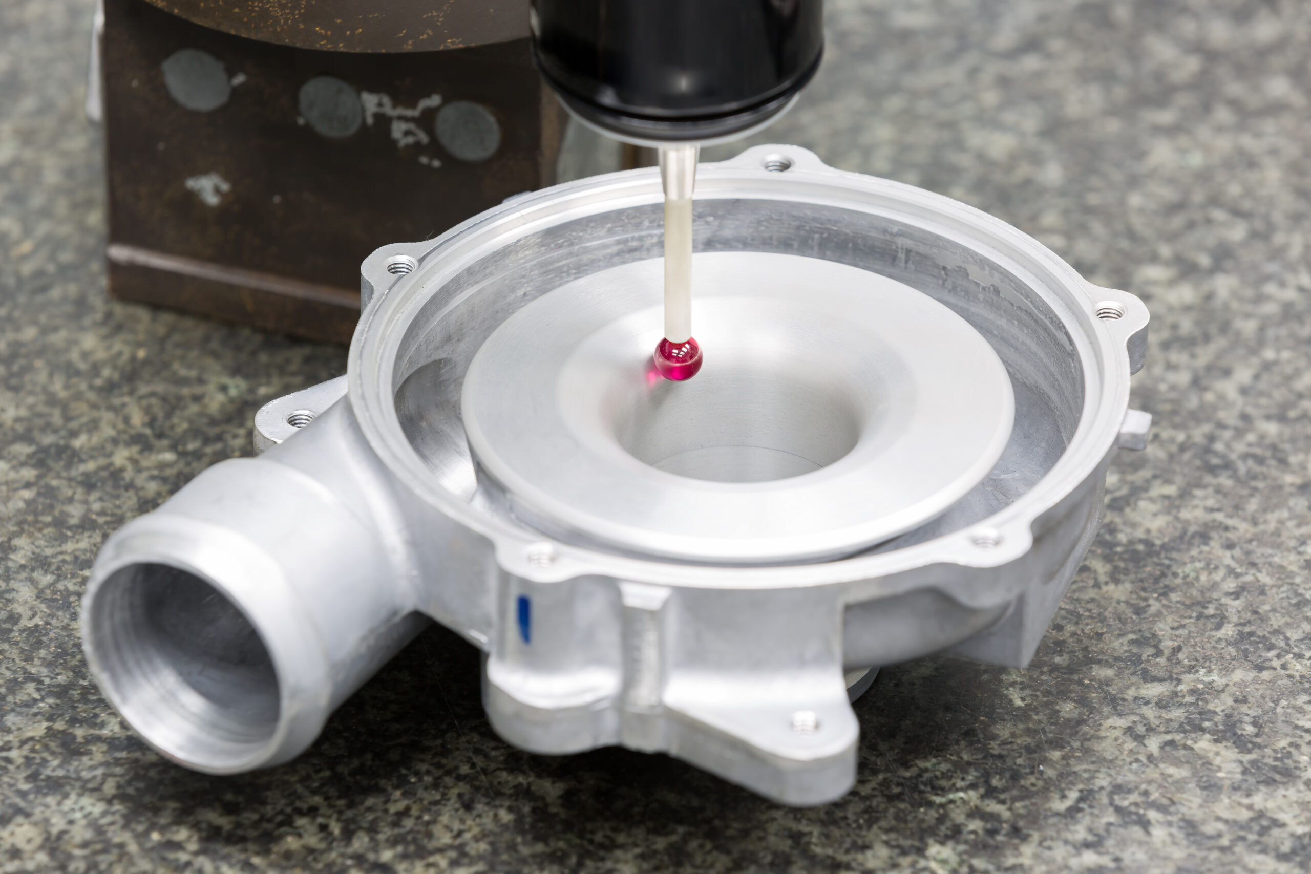
Touch probes can do a lot to help an operator improve their productivity and increase their job quality. Probes can help set a fixture’s location, calibrate a machine’s rotary axes, and check part alignment, among other utilities. The accuracy of a machine’s probe is going to be limited by several factors. Some major limitations include the accuracy of the machine, the accuracy of the probe, the probe calibration used, and the maintenance performed on the probe. It is important to understand the limitations of the touch probe and how to properly calibrate a probe for use on a machine tool.
Why Calibrate
Machine probes work in the simplest form by registering the level of force on the stylus and if this force exceeds a threshold signaling to the machine that a probe contact has occurred. This level of force must be something greater than zero and it must be an amount great enough that the inertia generated from accelerating the probe between points in the machine does not cause a false contact to be registered. Because the amount of force required to signal a contact has occurred is greater than zero a certain amount of deflection must occur before this force threshold is met. Touch probe calibration measures this amount of deflection and accounts for it when measuring points.
Types of Probes
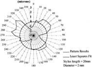 With the understanding of why calibration is important, it is also important to understand the different types of sensors used to register a probe contact. This understanding is important because the way the probe sensor works, determines its accuracy and repeatability. A common concept in touch probes is lobing. Lobing is a measurement of the varying amount of force in each direction required to register a probe contact. A touch probe with less lobing will be more accurate.
Kinematic Probes and Performance
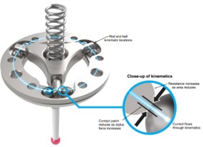
For machines with rotary axes that move the part such as a rotary table or trunnion-style machines, the rotary axes’
position does not affect the probe calibration, so in these cases, there is no additional calibration needed. However, for machines with rotary axes that move the tool like swivel or tilt head style machines, the calibration can be affected by the position of these rotary axes. In these cases, it is sometimes common to calibrate the probe at every angle of the rotaries that probe points will be taken and the corresponding rotary angles referenced when calibrating the probe hit.
Strain Gage Probes and Performance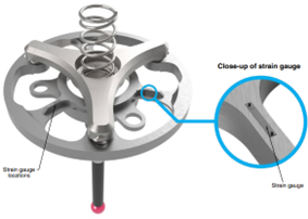
Strain gage probes work similarly to kinematic probes but replace the contact spheres with highly sensitive strain gauges. These gauges are very sensitive and result in a very small amount of lobing. They are also typically less prone to false contact triggers than kinematic probes.
Optical Probes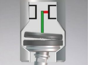
Optical probes work by shining a light, typically a laser, across the internal end of the probe stylus to a receiver. When the probe is contacted this causes the light on the receiver to be broken. Optical probes like kinematic probes have very low amounts of lobing.
Types of Calibration
There are two main types of probe calibration. Those are constant deflection calibration and variable deflection calibration. Each type comes with pros and cons, and each has its purposes. Additionally, calibration can help account for probe runout. Although some calibration will account for runout, the operator should do the best job possible to account for the runout of the probe by using the mechanical means of the probe to reduce its effect. During calibration, use the same feed rate as you use when running the probe for production.
Constant Deflection Calibration
Most operators commonly use and find that constant deflection calibration the easiest type of calibration. Typically accommodated by using either a ring gauge or a calibration sphere gauge, either tool will result in a similar result, and both require the operator to accurately input the radius of the gauge. Constant deflection calibration works by probing several points in a circle on the gauge and calculating the probe’s perceived radius of the gauge. Subtracting the difference between the actual radius of the gauge input by the operator and the measured radius found by the probe results in the amount of deflection required to trigger the probe. In the future, every time a probe hit occurs this difference can be added to the measured position of the probe to account for the deflection requirements of the probe.
Variable Deflection Calibration
Less common but often utilized for high-accuracy requirements in 5-axis machining, Variable Deflection calibration involves a longer runtime and always requires the use of a calibration sphere gauge. Variable deflection calibration works by probing a sphere at many different points along both its longitudinal and latitudinal axes. At each probe point, the difference between the expected location of the probe’s contact trigger and the actual location is measured. This data is stored resulting in a heat map of sorts on the sphere. In the future when a probe point is taken, its vector along which the probe point was taken is recorded and compared to the heat map on the sphere. That vector relates to a position on the sphere where the vector goes through the center of the sphere and the amount of deflection recorded during calibration at this point can be used.
A Note on Machine Kinematics
 For machines with rotary axes that move the part such as a rotary table or trunnion-style machines, the rotary axes’ position does not affect the probe calibration. However, for machines with rotary axes that move the tool like swivel or tilt head style machines, the calibration can be affected by the position of these rotary axes. In these cases, it is sometimes common to calibrate the probe at every angle of the rotaries that probe points will be taken and the corresponding rotary angles referenced when calibrating the probe hit.
Conclusion
A touch probe can be a very powerful tool in the hands of a skilled operator. Its capability is limited to its accuracy and its accuracy is directly related to how it is calibrated. If you probe is not properly calibrated the results may not be as accurate as needed for the application. Let NC Software Solutions work with your team to help your shop get the most out of your probes and expand your shop’s capabilities to include adaptive machining.
Works Cited
Blum-Novotest. (2023, 01 05). Touch Probe TC55. Retrieved from https://www.blum-novotest.com/fileadmin/benutzerdaten/blum-novotest-de/pdf/downloads/messkomponenten/messtaster/5-tc55/tc55-en.pdf
P.A Cauchick-Miguel, T. K. (1996). Factors which influence CMM touch trigger probe performance. International Journal of Machine Tools and Manufacture.
Renishaw. (2023, 01 05). Retrieved from Probing Systems for CNC Machine Tools: Probing_systems_for_CNC_machine_tools_technical_specifications_H_2000_3020_12.pdf
blog: Strain-gauge machine-tool probe is right for 5-axis aerospace parts
NCSS NC Transform software includes comprehensive probe calibration tools. For more information, please see NC Transform .
NCSS blog article: Optimizing CNC Performance with Touch Probe Calibration by Alex Mitchell 11-11-2023 all rights reserved
One Response
Nice article. Well done.