
NCTransform® Capability
Adaptive Morphing
Toolpaths That Follow Reality
Real parts don’t match the CAD model exactly. Castings warp. Extrusions bow. Edges shift. With NCTransform® morphing, your team can measure the actual part and adapt any toolpath to match, automatically. The math is handled by NCT. Your engineers define what to follow and push start
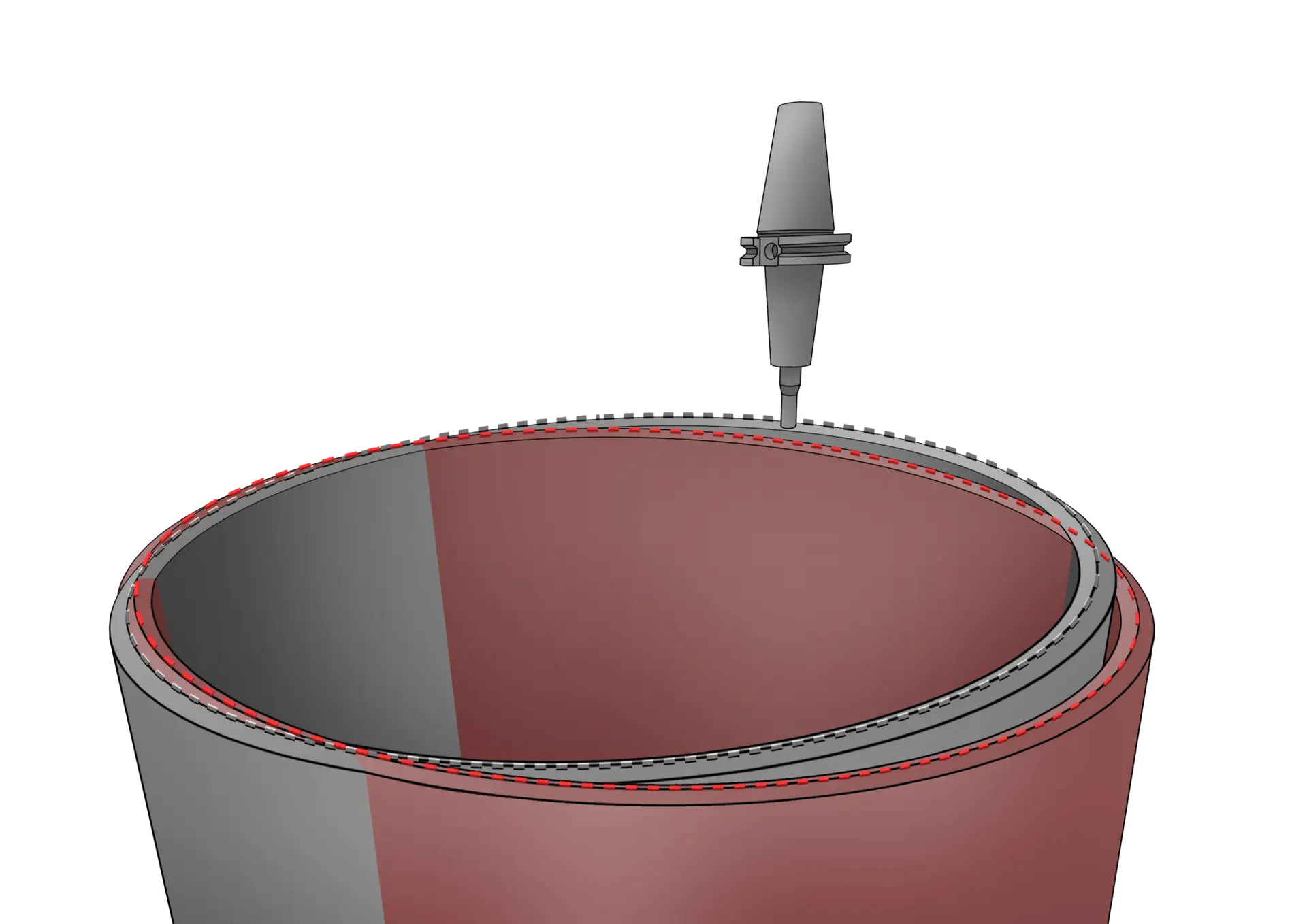
Nominal path vs. actual morphed path — ring edge following
4+ types
Spline, swept surface, ruled surface, cross-section: built for the full range of part variation your team encounters
Stacks
Combine with global orient and local alignment for complete, layered part control
Easy setup
Complex math handled by NCT. Your engineers define the approach and run it
Any sensor
Touch probing, drag scanning, light scanning, and ultrasonic thickness gauging
The core idea
Your program was written for a perfect part. The part isn't perfect.
Without morphing
Your program runs at nominal. The part isn't
With NCTransform® morphing
Your toolpath follows the actual part
Stacks with alignment
Morphing works alongside Global Orientation and Local Feature Alignment.
Your team can stack all three in a single NC program: global orient to find the part, local orient to fine-tune a specific feature, and morphing to follow the actual surface topology. Each layer adds precision. Each runs automatically.
Easy for engineers to set up
Morphing techniques
Multiple approaches. Right tool for every part.
Spline edge following
Morphing type 01
Spline edge following
Follow any non-nominal edge, holding consistent depth
Your team probes a series of points along an edge and NCT fits a spline through the actual measured positions. The toolpath morphs to follow that real spline, tracking the edge precisely regardless of how it deviates from nominal CAD geometry.
The result: seal slots, deburring passes, chamfering, and edge-following operations that maintain the correct depth relative to the real edge, even when that edge bows, tapers, or shifts from part to part.
Seal slot machining
Deburring
Edge chamfering
Attachment ring edges
Consistent-depth passes
Non-nominal edge following
- Nominal path
- Morphed actual path
Swept surface morphing
Morphing type 02
Swept surface morphing
Probe multiple splines, sweep a surface, remove consistent stock
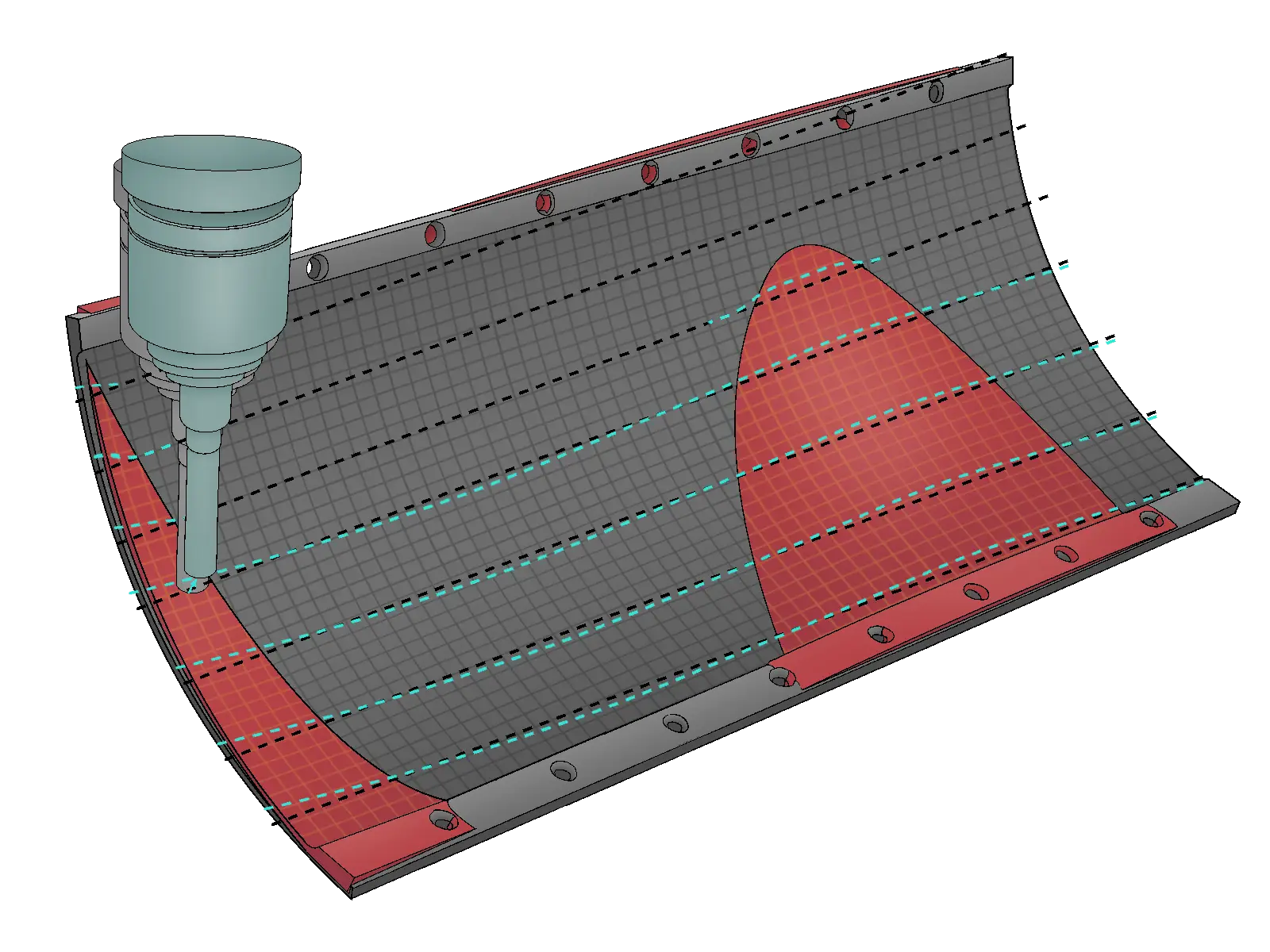
For parts with complex 3D surface variation: warped extrusions, bowed structural members, twisted profiles. Your team probes multiple cross-section splines along the part. NCT sweeps a surface through the measured points, reconstructing the actual 3D topology.
The toolpath then maintains a consistent offset from that swept surface, removing a precise, uniform amount of material regardless of how the part has warped or deviated. Ideal for structural components, longerons, and any part where the shape varies in multiple directions.
Warped extrusions
Bowed structural members
Consistent stock removal
Longerons & spars
Carbon fiber skins
Sheet metal formed parts
- Nominal surface
- Actual morphed surface
Ruled surface morphing
Morphing type 03
Ruled surface morphing
Define two edges. NCT rules the surface between them
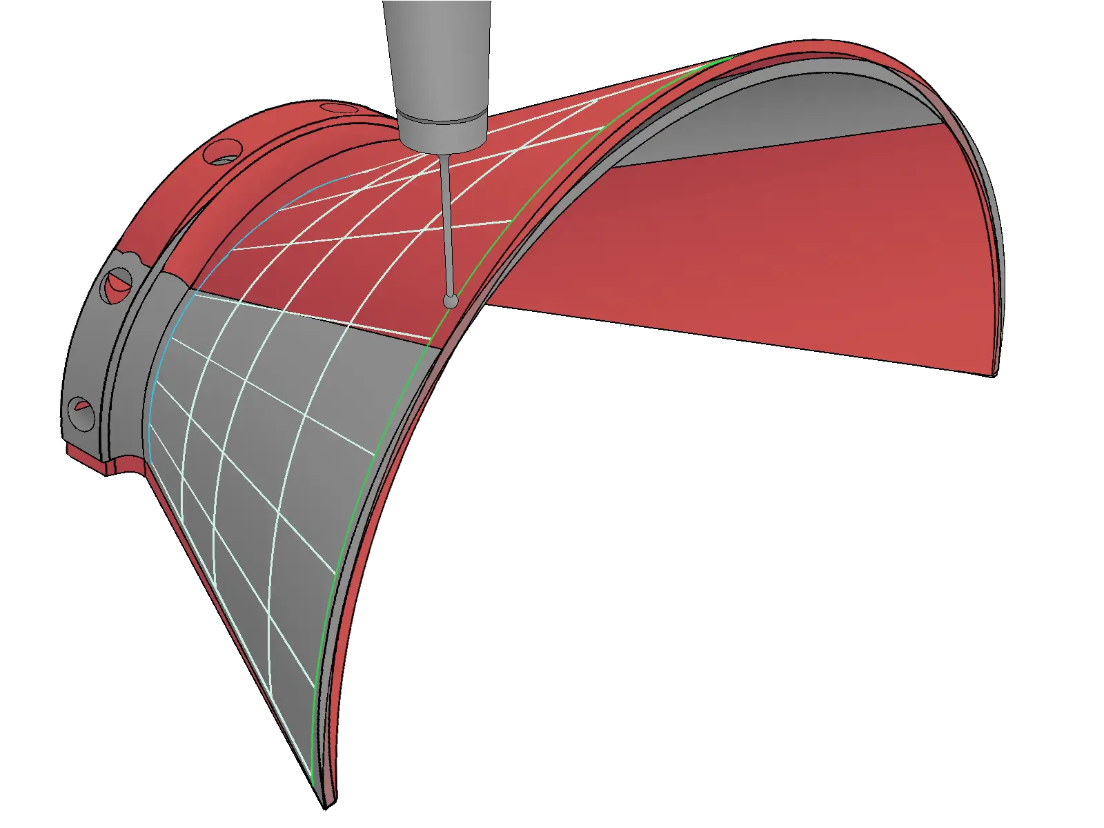
Your team measures two boundary edges and NCT constructs a ruled surface between them. A mathematically defined surface where every point lies on a straight line connecting the two edges. The toolpath morphs to follow that actual ruled surface.
Ideal for blade and vane profiles, tapered walls, and any geometry where the surface is defined by the relationship between two real edges rather than a standalone surface model. Handles edge-to-edge variation that swept surface morphing isn’t designed for.
Blade profiles
Tapered wall machining
Edge-defined surfaces
Vane trailing edges
Formed sheet metal
Structural ribs
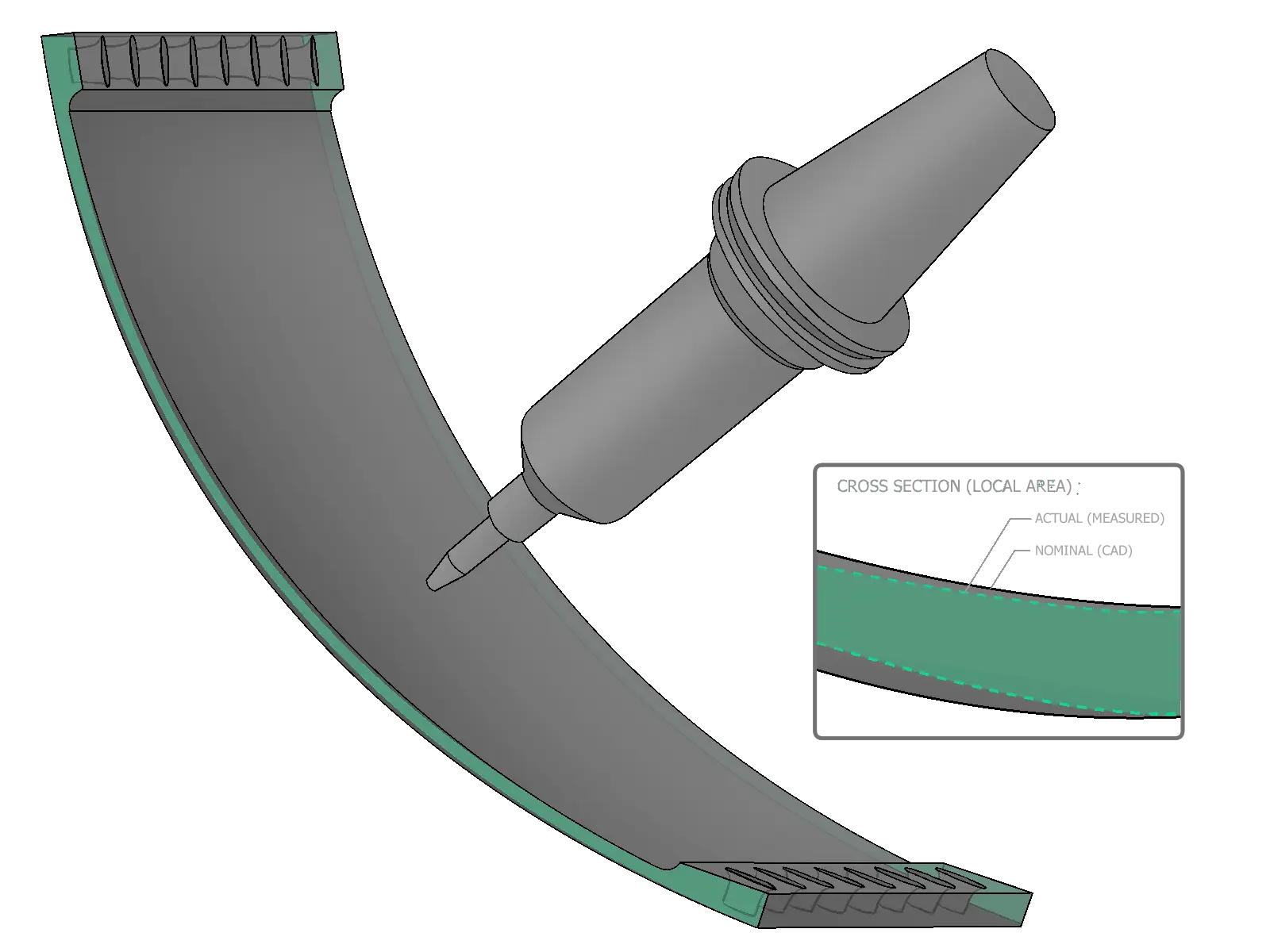
Cross-section morphing
Morphing type 04
Cross-section morphing
Control cutter angle and position independently at every section
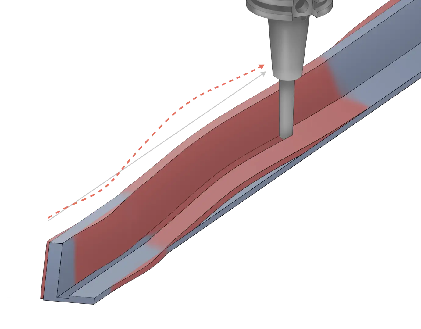
Your team probes a series of cross-sections along the part. At each section, NCT independently controls both the position of the toolpath and the angle of the cutter, adapting to the actual surface normal at every measured point.
The result: truly surface-adaptive machining where the cutter is always presented at the correct angle to the real surface, not the nominal model. Critical for 5-axis operations on complex aero surfaces where both depth and tool normal must be precisely controlled to hit the required surface finish and avoid gouging.
5-axis surface morphing
Complex aero profiles
Cutter normal control
Turbine vane machining
Airfoil profiling
Adaptive finishing passes
- Nominal surface
- Actual morphed path
Ultrasonic thickness morphing
Morphing type 05
Ultrasonic thickness morphing
Measure real wall thickness, hold it consistently across the part
For large deformed parts where wall thickness is critical: structural skins, fuselage panels, duct walls. Your team can use an ultrasonic thickness gauge probe to measure the real thickness at multiple points across the surface. NCT sweeps a surface through those measurements and morphs the toolpath to hold a consistent, defined wall thickness throughout the cut.
This is the only way to guarantee consistent thickness on a part that has warped or deformed because it measures what’s actually there, not what the nominal model says. No guessing. No overcut through the wall. No undercut that leaves too much material.
Structural skins
Fuselage panels
Consistent wall thickness
Duct walls
Large deformed parts
Thin-wall machining
How morphing works
Probe. Reconstruct. Morph. Cut.
01
Your engineer defines the probe pattern once
02
NCT measures the actual part. Your choice of method
03
NCT reconstructs the actual geometry
04
The toolpath is morphed automatically
05
Cut and verify before the part leaves
Measurement methods
Your team chooses how to measure the part.
Touch probing
Standard approach: discrete point measurement using your existing touch probe system.
Drag scanning
High-speed continuous scanning (Renishaw SPRINT), far more data points in the same time for complex curved geometries.
Light scanning
Non-contact optical scanning, delivering, high-resolution topology data without touching the surface.
Ultrasonic thickness
Measures real wall thickness at each point. The only way to guarantee consistent thickness on deformed parts.
See it in action
Toolpath morphing: live demo
Business impact
What your team gains from adaptive morphing.
Hold the right depth on every part
Whether it's a seal slot, deburring pass, or surface finishing operation. Your team holds the correct depth relative to the actual part surface, not the nominal model. Consistent results across all part variation.
Machine parts that would otherwise be scrap
Warped extrusions, shifted castings, bowed structural members. Your team can machine them successfully instead of scrapping them. NCT adapts to the actual part, not the theoretical one.
Any engineer can set it up
NCT handles the surface mathematics: fitting splines, reconstructing swept surfaces, controlling cutter normals across sections., sweeping surfaces, controlling cutter normals. Your engineer defines what to follow and NCT generates the adapted toolpath. Most prove out their first program the same day.
No manual path editing
Eliminate the cycle of measuring a deviant part, editing paths in CAM, re-posting, and re-running. Your team gets the adapted path automatically. In the time it takes to probe the part.
Use your existing programs and CAM
Morphing is applied at runtime to the existing NC program, no new post-processor, no CAM integration, no program rewrite. Your team starts with what they already have.
Win work your competitors can't do
Take on complex adaptive machining contracts involving deformed structural parts, variable extrusions, and thick-wall components that require capabilities most shops don't have. NCT gives your team those capabilities without specialized labor.
"
Consistent
Parts held within tolerance every run
Any part
Adapts to real geometry, not the model
No rework
First-run quality on variable parts
Other NCTransform® capabilities