
NCTransform® Capability

Local Feature Alignment

Per-Feature Datum Control

Some features need their own coordinate system, independent of where the part is globally. With Local Feature Alignment, your team can align to individual features and apply that alignment to any section of toolpath automatically, stacking on top of full part alignment for a complete layered datum scheme. Complex parts. One setup. No manual re-indicating.
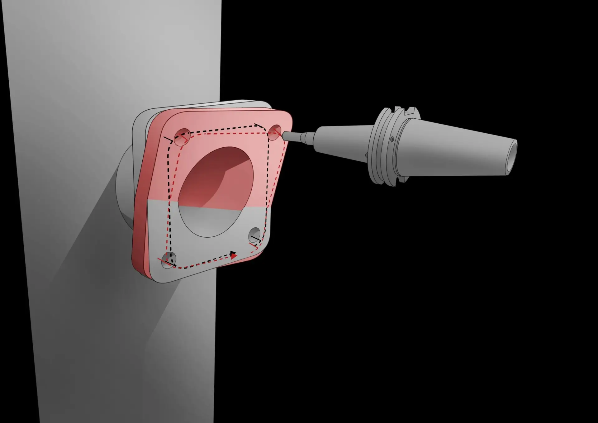
Probing hole pattern & bore on welded spud: local alignment in action

Stacks

Builds on global orientation. Your team gets a complete layered datum scheme in one program

Any feature

Bores, surfaces, walls, cones, hole patterns. If a probe can touch it, you can datum to it

Automatic

Push start: probing, alignment, and cutting all happen without operator intervention

Repeatable

Same result every part, every shift, every operator, no skill dependence

Local Feature Alignment builds on Global Orientation.

Your team can run a full part alignment first to establish the overall part coordinate system, then stack local alignments on top, each one targeting a specific feature with its own datum. Global gets you to the part. Local gets you to the feature. One program. One setup.

How it Works

Push start. Your team gets the feature.
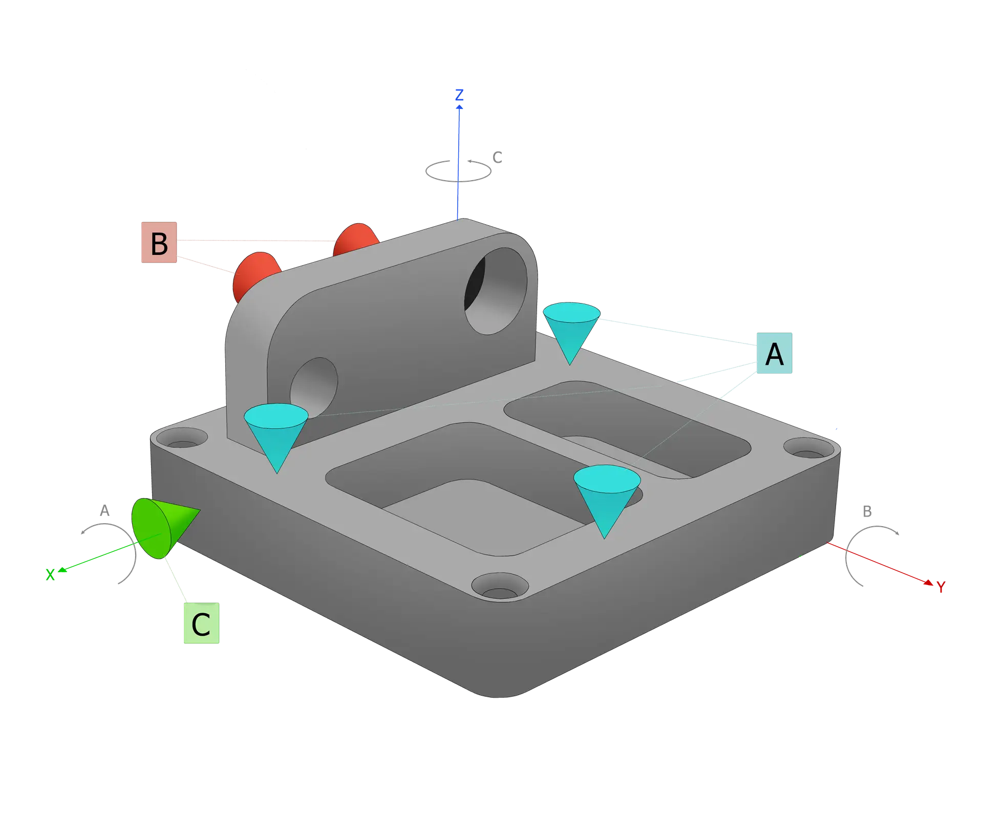
Your team pushes start and NCTransform® handles everything: probing the feature’s datum, computing the local transformation, and running the adapted cut program. No manual re-indicating. No offline processing. The same automated cycle runs for every part on every shift.

01

Global orientation first (optional)

If the part needs full part alignment, your team runs that first, establishing the overall part coordinate system. Local alignments then stack on top, each targeting a specific feature. Or run local alignments standalone. Either way, it’s one program.
Local alignments are fully independent and can be used without global orient, or layered on top of it. Multiple local datums can be defined in a single NC program, each applied to its own set of toolpaths.

02

NCT probes the local datum features automatically
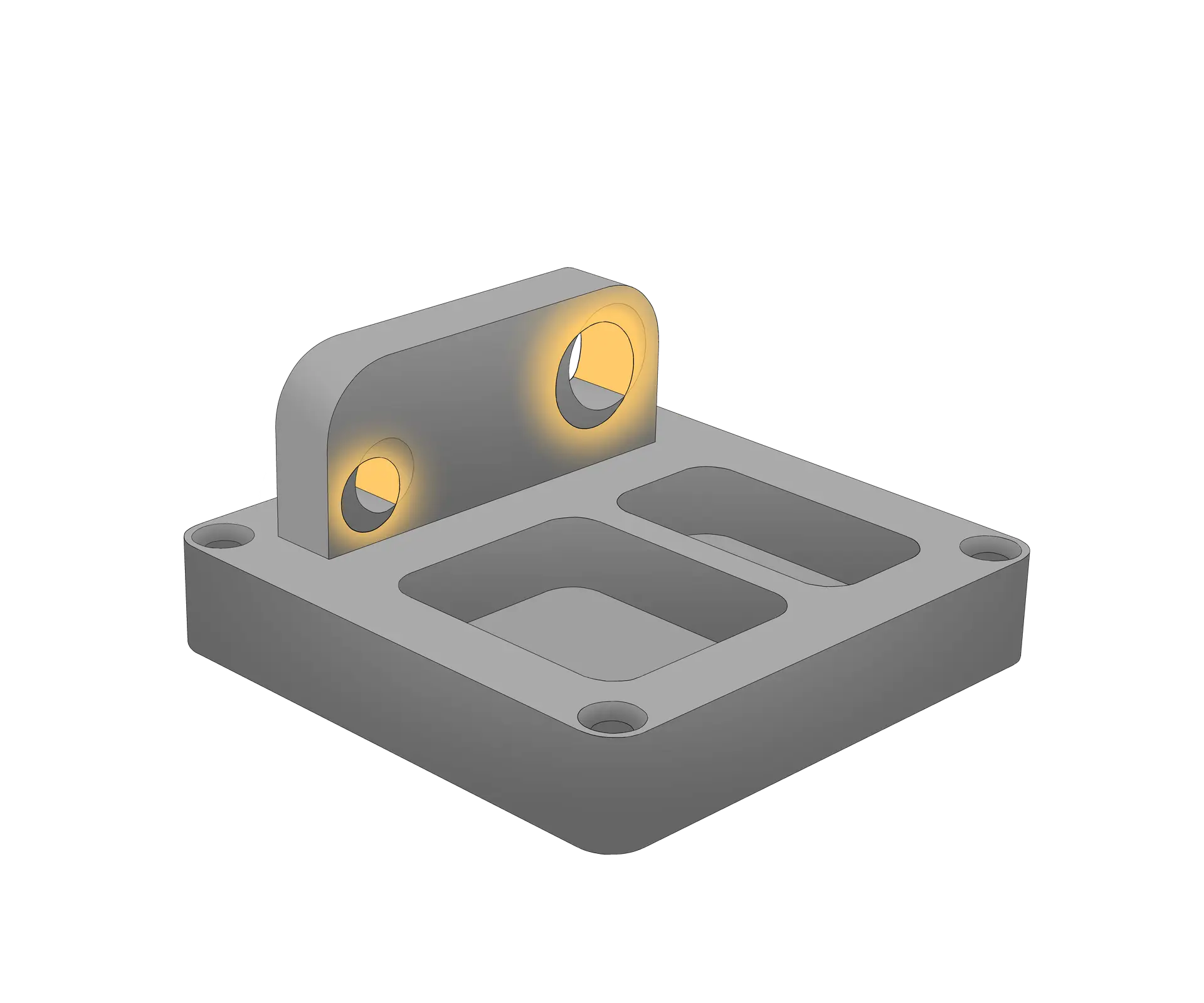
NCT probes to establish the feature’s actual position and orientation, simultaneously capturing everything needed to align the local coordinate system. No operator input required.
Multiple constraints are handled in one probe cycle. For example, probing a surface for tool vector perpendicularity and a bore for XY origin in a single pass. Your team gets both constraints resolved at once.

03

The local transformation is computed and checked
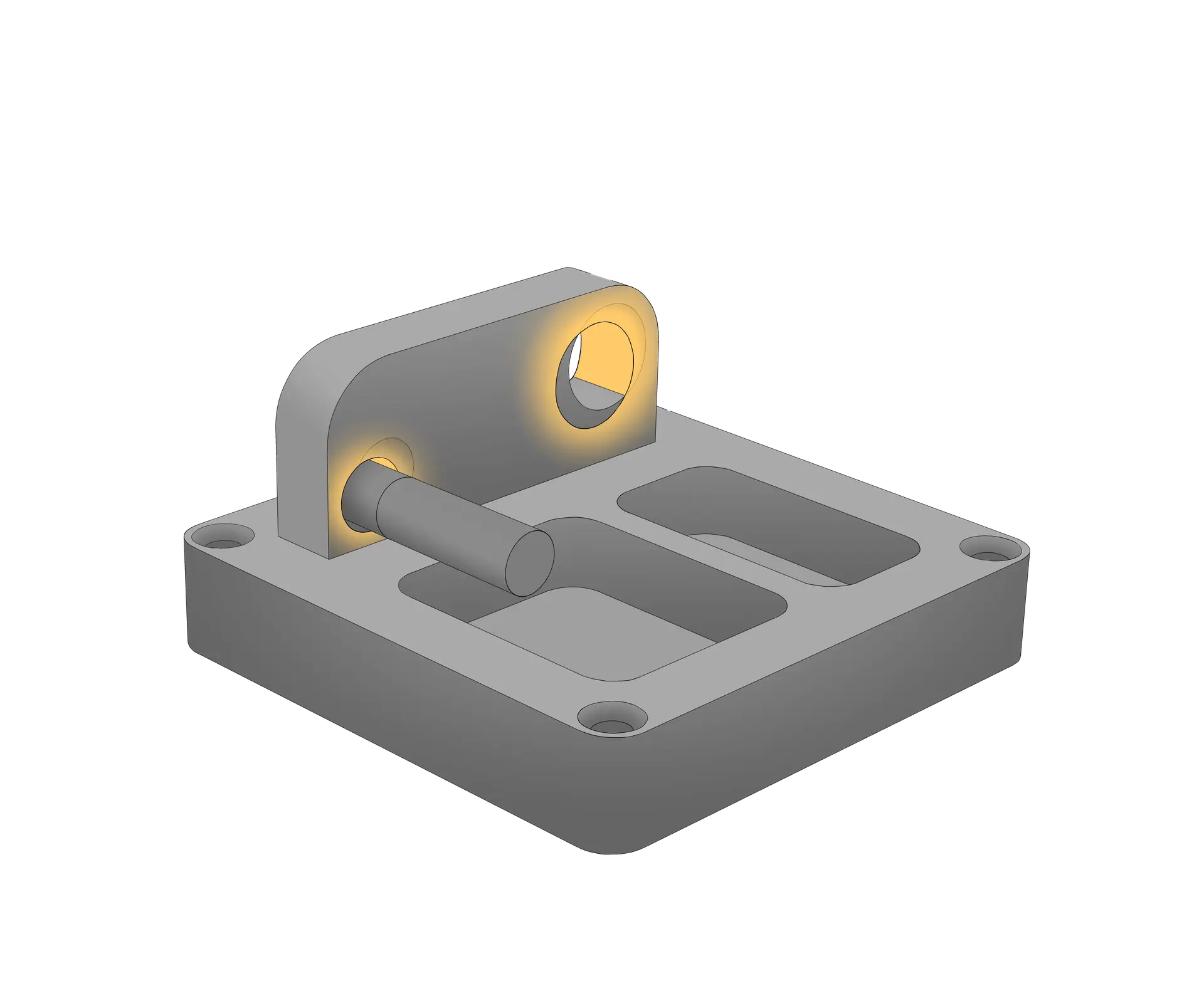
NCT computes the transformation that maps the nominal local coordinate system to the actual measured feature position. It then checks the result against your defined conformance limits: maximum allowable translation and rotation for that feature, before any toolpath runs.
If the feature falls outside conformance limits, NCT flags it before cutting begins. The alignment is then applied to the specific section of toolpath associated with that feature, leaving the rest of the program untouched.

04

Your toolpaths run against the actual feature

The toolpaths for this feature are transformed to the actual local position and the cut program runs. Your team gets accurate, repeatable results on every part, regardless of how the weld landed or how much the feature shifted from nominal.
After machining, NCT can optionally re-probe the feature to verify the result and generate an inspection record. All before the part leaves the fixture.

Step by step: welded spud example

From nominal to actual, one feature at a time.
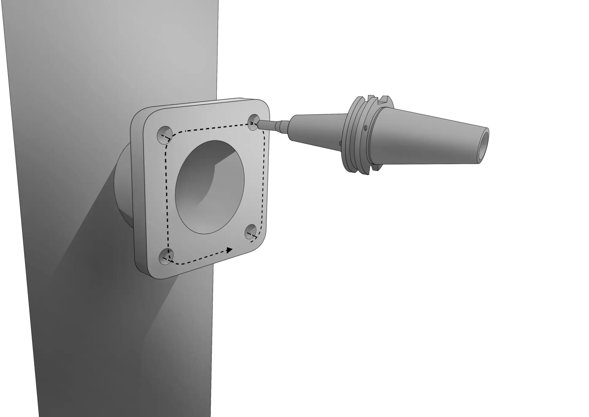
The sequence below shows a welded-on spud. A classic local alignment challenge. The spud’s position shifts from nominal due to weld distortion. Your team loads the part, pushes start, and NCTransform® finds it, probes it, and cuts it accurately, automatically.

Step 01 — Nominal

Program written to nominal
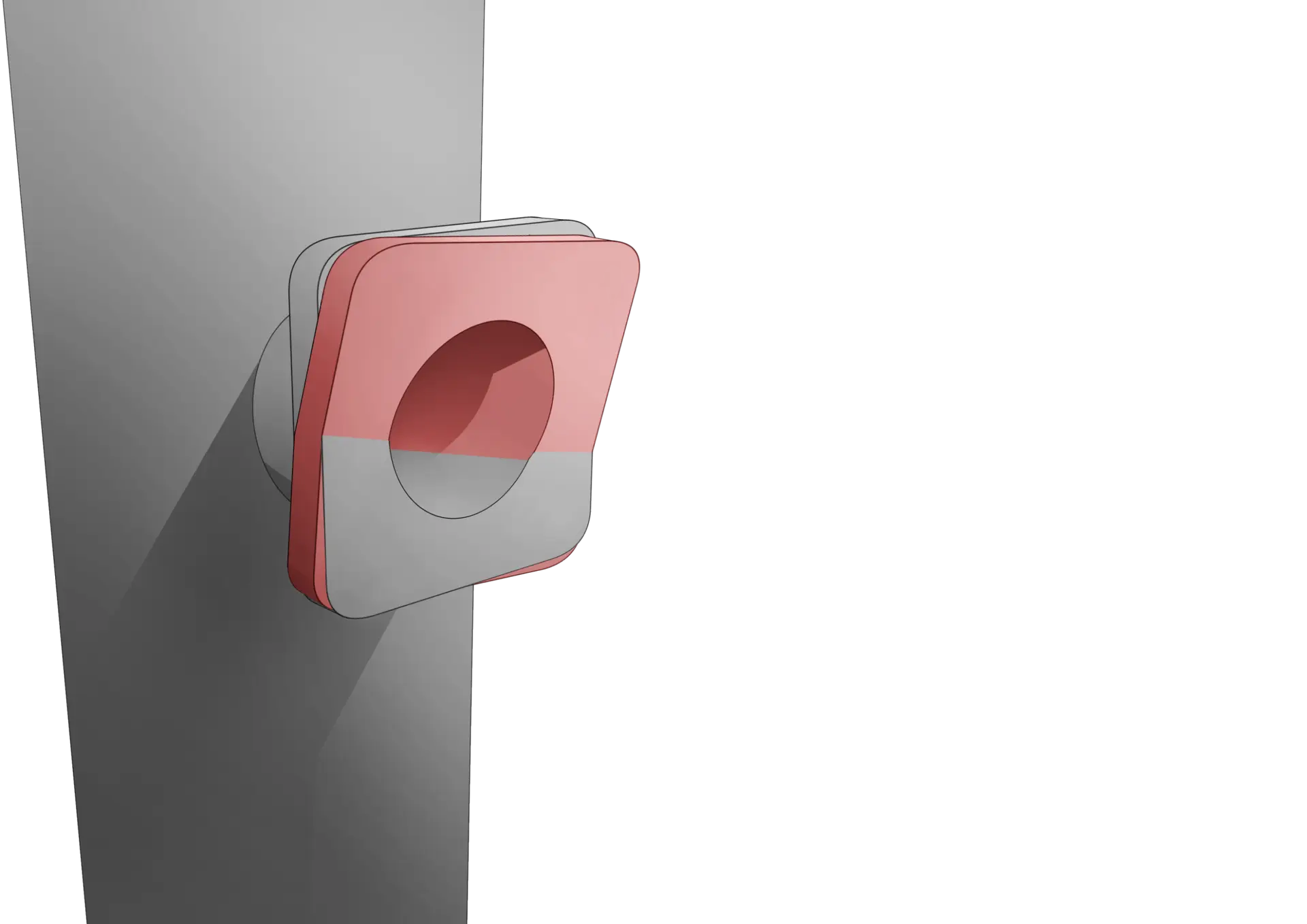
Your NC program is written to the nominal CAD position of the feature. Everything looks correct on the model, but the real part tells a different story.

Step 02 — Variation found

Feature offset from nominal
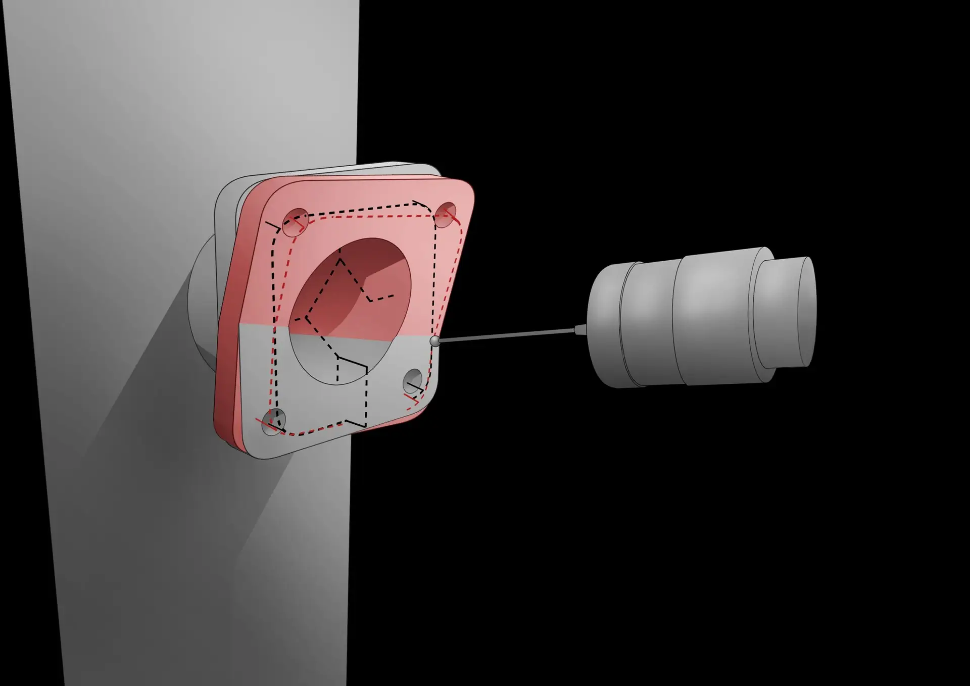
The welded spud has shifted and rotated from its nominal position due to thermal distortion, weld variation, or fixturing inconsistency. NCT has already measured it and computed the correction.

Step 03 — Probe

NCT probes the surface and bore

NCT probes the actual surface to establish the tool vector and the bore to establish the local origin. Aligning the hole pattern toolpath to the real feature position, not the nominal one.

Step 04 — Aligned

Toolpath transformed. Ready to cut.

Your toolpath is transformed to match the actual feature. The cut program runs against the real part datum. Your team gets an accurately machined feature regardless of where the weld landed.

Use cases

Where your team can put local alignment to work.
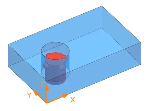
Any time a feature has its own datum structure, independent of the overall part orientation. Your team can use local feature alignment to machine it accurately without manual re-indicating.

Hole pattern following a bore

Your team can machine a bolt hole pattern to true position relative to a bore, automatically. NCT probes the bore to establish the local origin, aligns the hole pattern toolpath to that measured center, and holds surface perpendicularity simultaneously. No manual indicating of the bore required.

Typical applications

Flanges

Bosses

Aerospace brackets

Engine casings

Structural casings
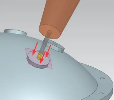
Tool vector perpendicular to a surface

Your team can drill, ream, or mill perpendicular to any surface, even when it’s tilted relative to the machine axes. NCT probes the surface normal and rotates the tool vector to match the actual surface, not the nominal. Critical for hole geometry and surface finish on complex geometry.

Typical applications

Drilling on curved surfaces

Normal vector alignment

5-axis positioning

Countersinking
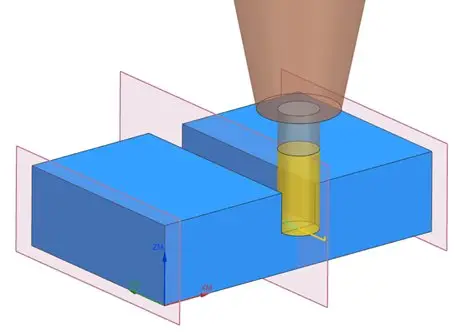
Midline between two parallel walls

Your team can center toolpaths in slots, pockets, and channels automatically, even when wall spacing varies. NCT probes both walls and computes the true midline, ensuring even stock removal and symmetric finished geometry without manual measurement.

Typical applications

Slots & keyways

Pockets

Splines

Dovetails

Cast channels
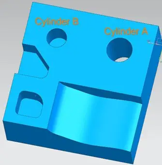
Cylinder-to-cylinder alignment

Your team can machine a cylinder to match the actual axis of another, ensuring concentricity, coaxiality, or a precise angular relationship between two bores or bosses. NCT probes the reference cylinder to establish the local axis, then aligns the toolpath for the mating feature to match. No manual shimming or angle-finding required.

Typical applications

Concentric bores

Coaxial features

Bearing journals

Shaft alignments

Engine casings
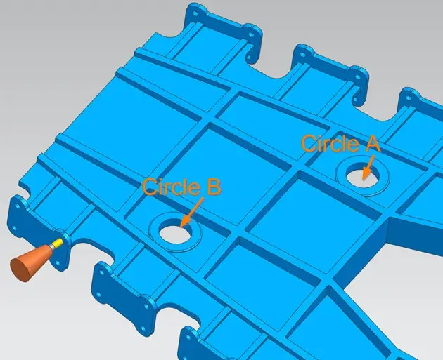
Secondary datums stacked on global orientation

Your team can build a complete datum hierarchy: global orient for the part, local alignments for each critical feature. All in one NC program, one setup. Complex multi-datum aerospace castings that previously required multiple setups and skilled machinists can now be run by any operator.

Typical applications

Multi-datum castings

Complex aerospace parts

Engine housings

Structural frames

Defense components

See it in action

Local feature alignment: live demo

Watch NCTransform® probe a welded spud’s hole pattern and bore, then automatically align and execute the machining cycle to the actual feature position.

Business impact

What your team gains from local feature alignment.

Hit true position on every part

Your team uses NCTransform® to machine hole patterns, bores, and features to their correct position relative to the local datum, not the global part origin, regardless of how the part was fixtured or how the weld landed.

Eliminate re-indicating after welding

Your team loads the part and pushes start. NCT probes and aligns every weld feature automatically, no manual re-indicating, no operator skill dependence, every part.

Handle any amount of part variation

Weld distortion, casting shift, forging inconsistency. Your team uses NCTransform® to handle it all automatically. Each part is measured and aligned individually, so variation never becomes scrap.

Build a full datum hierarchy in one program

Your team runs global orient plus multiple local alignments in a single NC program, one setup, no re-fixturing, no multiple programs to manage. Complex multi-datum parts become routine.

Use your existing programs and CAM

Local alignments are applied at runtime. Your original NC program is unchanged. No new post-processor, no CAM integration, no program rewrite. Your team starts with what they already have.

Verify on the machine before release

After machining, your team can opt to re-probe the local features to verify the result and generate an inspection record. All before the part leaves the fixture. Catch any issue while you can still fix it.

"

"We had a process where we constantly struggled to hold angularity on a boss feature. It would go to the CMM, and it was a gamble whether it would pass or fail — and a failure meant an expensive customer submittal process. Since we implemented NC Transform, that problem has gone away completely."
J. Schultz
Manufacturing Engineer

Gone

Angularity failures that plagued the process: eliminated

No gamble

CMM results are predictable, not a coin flip

No submittals

Expensive customer failure process avoided entirely

Have a feature your team can't reliably indicate?

Tell us about your part. We’ll show you exactly what your team can do with local alignment.